How would you like to talk over a laser beam? In about 15 minutes you can set up your own laser communication system, using cheap laser pen pointers and a few extra parts.
For the transmitter you will need:
- A laser pen pointer. You can get one from our catalog.
- A battery holder that holds the same number of batteries as the laser pointer (often 3 cells). The batteries can be any size, but they must be the same voltage as the laser batteries. You may need to get one that holds two cells, and another that holds one cell, and wire them together in series. We offer a nice one in our catalog, and we also offer a kit for the entire project.
- A transistor radio. Later we will use a microphone and an amplifier (Radio Shack #33-1067 and #277-1008), but at first we will send your favorite radio station over the laser beam.
- An earphone jack that will fit your transistor radio (Radio Shack #42-2434).
- A transformer of the type known as an audio output transformer. It consists of an 8 ohm coil and a 1000 ohm coil. The one I used is the Radio Shack #273-1380. We now carry them in our catalog.
- Some clip leads (wires with alligator clips on the ends) to put it all together. At least one of the clip leads should be the type with a long slender point (Radio Shack #278-016, #270-372, or #270-334), to connect to the inside of the laser pointer. You can substitute regular wire and solder if you like, but the clip leads are fast and simple. Radio Shack has a wide selection of clip leads (such as ##270-378).
- A two-lead bicolor light emitting diode, to protect the laser from high voltage spikes.
-
For the receiver you will need:
- A small solar cell (such as Radio Shack #276-124). You may have to solder your own wires to it if it doesn't come with wires attached.
- A microphone jack that will fit the phono input of your stereo (Radio Shack #42-2434 or ##42-2457). Instead of a stereo, you can use the small amplifiers that Radio Shack sells (#277-1008).
It may be hard to find a battery holder that holds three batteries. You can use two battery holders (one that holds two batteries, and one that holds a single battery) and connect them in series.
Remove any batteries from the laser.
Connect a clip lead to the inside of the laser pointer where the battery touched. Usually there is a small spring to which you can attach the clip lead. The other end of the battery usually connects to the case of the laser. Since there are many different styles of laser pointer, you may have to experiment with clip lead placement to get the laser to work with the new external battery pack. You may also have to hold down the laser's push button switch by wrapping a rubber band or some wire around it. Test the connection before you attach the transformer, to make sure the laser works with the new battery pack. If it doesn't light, try reversing the battery. Battery reversal will not harm the laser.
Connect the 1,000 ohm side of the transformer between the battery and the laser. The 1,000 ohm side of the transformer has three wires coming from it. We only use the outside two wires. The inside wire is called a center tap and we do not use it in this circuit.
Connect the bicolor light emitting diode to the two outside wires of the transformer on the 1,000 ohm side. We are using this part (the bicolor LED) as a protection device to prevent the laser from getting high voltage spikes from the transformer. We didn't need to do this with the old-style lasers that had protection circuits built into them, but there are a lot of lasers being sold lately that have no protection, and need the bicolor LED to absorb any extra high voltage the transformer may produce when it is connected or disconnected. If you see the LED flash when you connect the battery, you will be seeing it absorb a high voltage spike that might have otherwise damaged the laser.
Test the laser by attaching the battery. The laser should operate normally at this point.
Connect the earphone jack to the 8 ohm side of the transformer. The schematic of the transmitter looks like this:
The transformer modulates the power going to the laser. The signal from the radio is added to and subtracted from the battery power, and the laser gets brighter and dimmer along with the volume of the music or voice in the signal.
The receiver is the simplest part. You simply connect the solar cell to the microphone jack, and plug it into the amplifier or stereo phono input. It does not matter which way the wires are connected to the solar cell.
Here is the schematic of the receiver:
Setup and testing
Make sure the transistor radio is turned off, and the laser is on. Plug the earphone jack of the laser into the earphone socket of the radio.
Connect the solar cell to the amplifier or stereo, and turn the volume up until you hear a hissing noise, then turn it down slightly until the hiss isn't noticeable. The volume control should be fairly high, corresponding to an ear splitting level if it was playing music.
Aim the laser across the room so it hits the solar cell. You might hear clicks or pops coming from the stereo or amplifier as the laser beam passes over the solar cell. This indicates that everything is working fine at this point.
Now carefully turn on the radio and slowly adjust the volume until you hear the radio station voices or music coming from the amplifier across the room. The radio should be just audible if the earphone jack is pulled out, not loud. If you can't hear the sound from the amplifier across the room, make sure the laser is shining on the solar cell, then try increasing the volume of the amplifier before you increase the volume of the radio.
At this point you should be hearing the radio station coming in loud and clear in the amplifier across the room. Put your hand in front of the laser beam to break the connection, and notice that the music stops. Wiggle your fingers in the beam and listen to the music get chopped up by your fingers. Your laser communicator is ready for the next step.
To send your voice over the laser beam, you simply replace the transistor radio with a microphone and amplifier. Radio Shack sells small amplifiers (about the same size as the transistor radio) that have sockets for microphones and earphones. You can also use another stereo system, but be very careful with the volume control to prevent damage to the laser.
Using a disassembled laser pointer.
For this project we have removed the laser assembly from a small $10.00 laser pointer. The power supply circuit is the green board attached to the brass laser head. We carry similar laser pointers in our catalog that are easily disassembled for this project.
The laser below has voltage spike protection on the circuit board. The one you get may not have this, and so you will want to put a bicolor LED across the transformer like we did in the previous version.
The power supply circuit came conveniently marked with a plus and a minus next to two holes in the board. We solder the black negative lead from the battery clip to the hole marked minus. We solder one of the 1000 ohm coil leads to the hole marked plus. We solder the red positive lead of the battery clip to the other lead from the 1000 ohm coil.
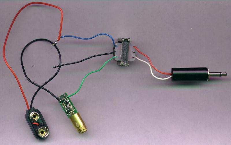
The battery clip is attached to a 4.5 volt battery pack (not a 9 volt battery!). Since I didn't have a pack that takes 3 cells, I used one that takes 4 AA batteries, and I replaced one of the four batteries with a straight piece of bare wire.
That's it! We have a laser transmitter, in just a few minutes!
A new receiver
The solar cell receiver has some drawbacks. It is expensive (solar cells are a few dollars each), and fragile.
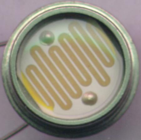
A cheaper, sturdier alternative is to use a cadmium sulphide photoresistor instead of the silicon photocell.
A cadmium sulphide photoresistor is shown below (magnified many times). It does not produce electricity from light the way the solar cell did. Instead, the light that falls on it changes its resistance to electricity.
If we connect a battery and a photoresistor together, they can act like the solar cell. As the intensity of the light changes, the amount of electricity output changes in response.
The new receiver is very simple, and looks like this:
Super simple receivers
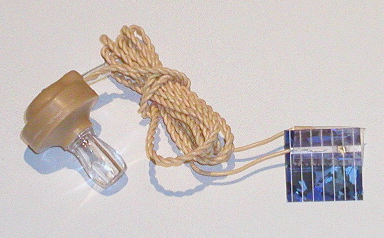
Using a super sensitive piezoelectric earphone (see our catalog), you can make a laser voice receiver that doesn't need any expensive amplifiers or power source. Just connect it to a small solar cell, as shown below:
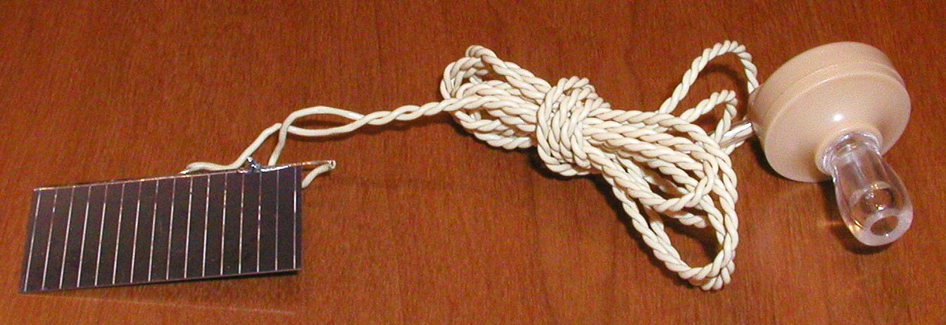
Also in our catalog, we have tiny silicon solar cells that you can attach to a piezoelectric earphone with simple transparent tape, instead of soldering (which can be difficult to do on silicon solar cells).
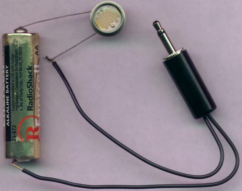
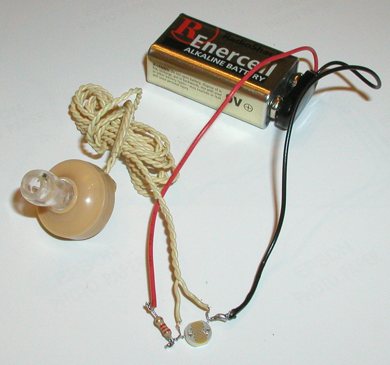
If a solar cell is too expensive or fragile, a cadmium-sulfide photoresistor can also be used. The earphone wires are connected across the photoresistor, and the battery is also connected across the same wires. The battery, the earphone, and the photoresistor are in parallel. A 220 ohm resistor is placed in series with the battery, to reduce power consumption, and prevent heating of the photoresistor.
Either of these earphone approaches has the nice feature of making the communication private. Only you can hear what is coming over the secret laser link.
How does it do that?
In all of the laser communicators on this page, the laser light is amplitude modulated. This simply means that the amount of light the laser emits varies over time.
To understand what is going on, it helps to consider how a loudspeaker makes sound. A loudspeaker is a paper cone attached to a coil of wire that sits in a magnetic field from a strong permanent magnet.
When an electric current flows in the loudspeaker coil, the coil becomes an electromagnet, and it moves toward or away from the permanent magnet. As it moves, the paper cone pushes on the air around it, compressing the air in front of it, and expanding the air behind it. Waves of compressed and expanded air travel to your ear, and cause your eardrum to move in time to the movements of the paper cone.
The laser communicator adds two components to the loudspeaker concept. We take the electrical signal that goes to the loudspeaker, and connect it instead to the laser, so the laser gets brighter and dimmer as the electric current varies. The second component is the receiver, which converts the light back into an electric current. This current varies in time with the first current, because the amount of light that it receives is varying in time.
This second electric current is used to move the paper cone of a loudspeaker, just as before. However, now the loudspeaker can be quite a distance away from the original electric current, without any wires connecting the two.